October 2018
Recently a specialty chemical plant in Canada had an issue with a waste storage tank that contained some environmentally “unfriendly” contents. The outflow valves from this holding tank were slowly decaying and even with redundant valving there appeared to be no way to replace the faulty valves without draining down the entire tank. The contents of the tank were going to require very expensive specialty hazardous material teams, tankers, storage and disposal to drain and remove. The company contacted COB industries with their situation to see if it was possible to freeze the contents of the outflow line to allow for repair. The conversation revealed that many of the general guidelines suggested by COB for freeze site selection were in question.

1) proximity to a potential heat source. The outflow line was welded directly to the wall of the storage tank which would act like a heat sink when trying to attempt a freeze. 2) Distance to a closed valve. A series of redundant valves were placed very close together going downstream from the storage tank wall. This included an encapsulated valve that had been leaking for quite some time. 3) Distance to a valve or fitting. In this case a flange connection was only 5” away from the only available freeze site. The standard 2” Accu Jacket was just over 8” long. All of these factors created what would typically be a “no go” situation for a freeze selection but with limited options it was agreed to attempt to freeze the line. A COB freeze technician was dispatched to the site and after a walk through and series of discussions with plant staff the okay was given to attempt the freeze. To make matters worse the area was experiencing a heat wave and the freeze location was in direct sunlight with no way to shade the area.

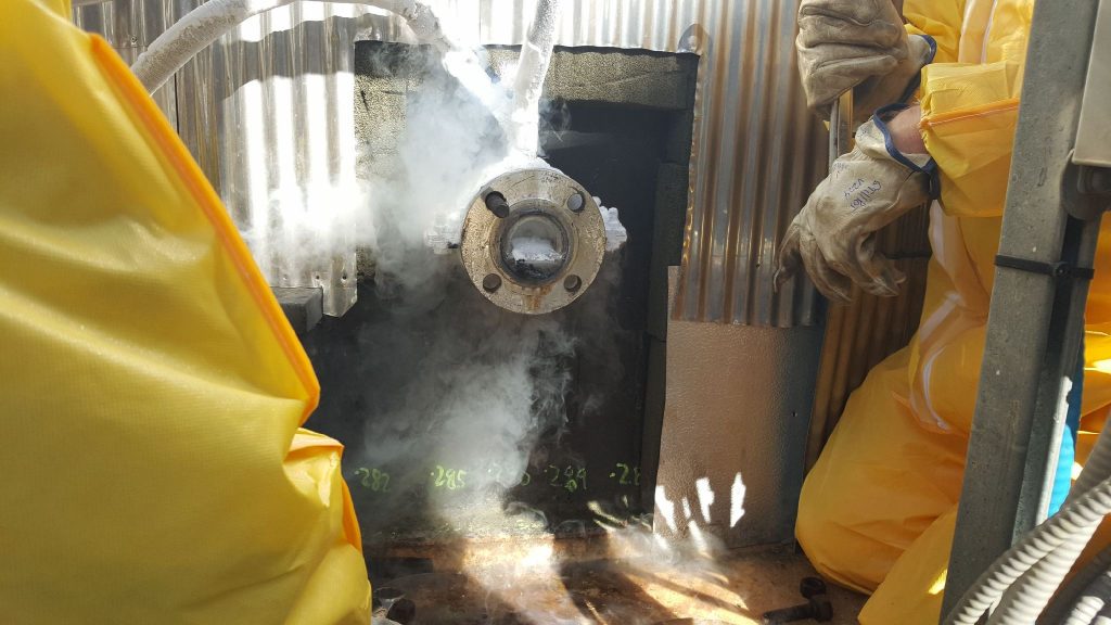
A custom 2” Accu Jacket had been built to fit precisely between the tank wall and the flange and the fit turned out to be nearly perfect. Only a little trimming of one of the bolts was required to make a good connection. Extra LN was bought in and staged nearby as it was expected that more time and nitrogen would be required to freeze the 2” line due to the tank wicking temperature away from the freeze site, the ambient conditions. Not to mention the unexpected placement of heat tracing on the outflow lines running year round(normally a 2” line would take approximately 30 minutes to freeze). The leaky valving actually helped in this situation because it allowed for visual confirmation of the freeze when the constant dripped stopped after 50 minutes. It was suggested that the freeze be held for another 10 minutes with all of the downstream valves held open and this confirmed the freeze integrity. The flange was unbolted and the concerns of a freeze plug stretching across the 2 flange faces making separation difficult (or impossible) were unproven as the ambient conditions prevented more growth of the ice plug and only a little trimming with a quickly fashioned “ice plug trimming tool” (a hacksaw blade with protective handle made by duct tape at one end) cleared away the ice and allowed for quick fitup of the new manifold by plant personnel.